Short manual for Nova 200, details of GUI
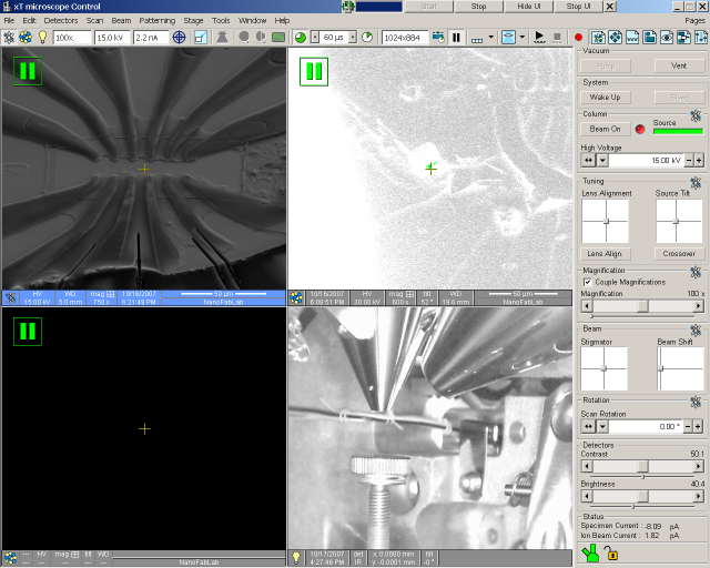
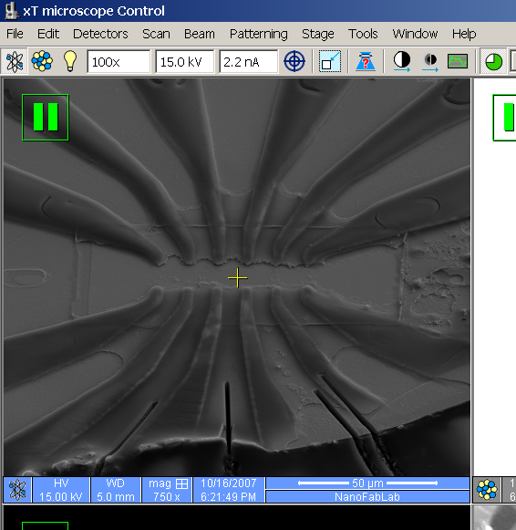
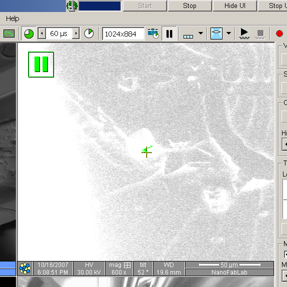
The selected quadrant (with blue info area at the bottom) can be made full screen by key F5. This is a toggle function, to get back to quad-mode, press F5 again.
|
|
 Symbol of electrons indicating that the SEM column is assigned to
this quadrant, this button is depressed.
Symbol of electrons indicating that the SEM column is assigned to
this quadrant, this button is depressed.
 Symbol of ions for assigning the FIB column to a quadrant.
 Symbol of lamp for assigning the CCD-camera to a quadrant.
 Quick selector for predefined magnifications
 Quick selector for predefined voltages
 Quick selector for predefined currents. This system has a condenser
lens, which makes it possible to get continuously variable current from one
aperture. To actually change aperture a mechanical knob must be
rotated on the SEM column.
Quick selector for predefined currents. This system has a condenser
lens, which makes it possible to get continuously variable current from one
aperture. To actually change aperture a mechanical knob must be
rotated on the SEM column.
 Focus wobble for lens alignment.
 Sub-window scanning, only part of the image field is scanned.
Good for reducing noise and still keep a reasonable image frequency.
Sub-window scanning, only part of the image field is scanned.
Good for reducing noise and still keep a reasonable image frequency.
 Locking Z-position to Working Distance. This is for telling the software
how high the sample really is, i.e. allowing the software to
autmatically calculate a new WD when Z is changed, thereby keeping
a good focus.
It is greyed out when the scanning is suspended (paused).
Locking Z-position to Working Distance. This is for telling the software
how high the sample really is, i.e. allowing the software to
autmatically calculate a new WD when Z is changed, thereby keeping
a good focus.
It is greyed out when the scanning is suspended (paused).
 Auto-brightness and contrast
 Auto-focus
 "Oscilloscope"-mode, intensity profile displayed over image
during scanning.
"Oscilloscope"-mode, intensity profile displayed over image
during scanning.
 Slow scan, to get a good, noise-free image when all settings have
been optimised.
Slow scan, to get a good, noise-free image when all settings have
been optimised.
 Scan-rate selector, indicated is the time spent in each pixel to
collect signal (electrons or ions).
Scan-rate selector, indicated is the time spent in each pixel to
collect signal (electrons or ions).
 Quick scan rate, to get a rather noisy image with high update rate,
good for making adjustments.
Quick scan rate, to get a rather noisy image with high update rate,
good for making adjustments.
 Image size selector, can be set to bigger sizes that screen can show,
but image is saved in the resolution set here.
Image size selector, can be set to bigger sizes that screen can show,
but image is saved in the resolution set here.

 Pause the scanning for the selected quadrant.
 Select mode of scanning, continuous averaging, scan and average a predefined
number of images. This mode is important when scanning images with FIB
column, since the ion beam can be very destructive to the sample.
Select mode of scanning, continuous averaging, scan and average a predefined
number of images. This mode is important when scanning images with FIB
column, since the ion beam can be very destructive to the sample.

 Select "Immersion"-mode, high resolution mode, only usable
for SEM column. Warning! Immersion mode
turns on a very strong magnetic field at the end of the SEM column, thus
making it very dangeruos to use lumps of magnetic material as samples!
Select "Immersion"-mode, high resolution mode, only usable
for SEM column. Warning! Immersion mode
turns on a very strong magnetic field at the end of the SEM column, thus
making it very dangeruos to use lumps of magnetic material as samples!
 Start etching or deposit defined patterns.
 Stop etching or deposit defined patterns.
 Start recording GUI actions as a macro.

|
Point and press left mouse button on horizontal line, BESIDE small square,
to adjust ONLY in vertical direction.
Point and press left mouse button on vertical line, ABOVE/BELOW small square, to adjust ONLY in horizontal direction. Point and press left mouse button on the small square and drag, then you adjust both horizontally and vertically. |
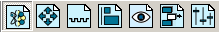
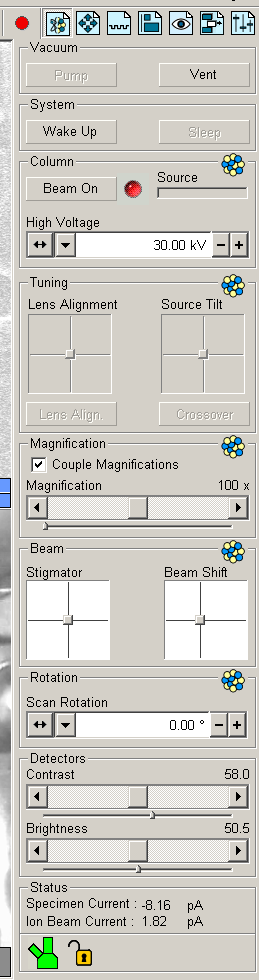
These various buttons select which parameters are shown in the area below. Here the first button is active, it is half electron symbol and half ion beam symbol. When this button is active the field below shows either SEM or FIB column parameters depending on which quadrant is activated.
Here are the parameters for the SEM column indicated by the
"electrons"-symbol, .
| Select buttons for parameter sets below |

|
| Pump or Vent for loading/unloading samples | |
|
Wake Up starts both SEM column and FIB column,
Sleep shuts them both off.
Please use Sleep when you have finished using the ion-source. It prolongs the lifetime. | |
|
Status for the selected column, in this case SEM, the FEG (Field
Emmision Gun) is fully operational, indicated by the green bar.
The High Voltage is not on, indicated by the Beam On button is not active and the red indicator light. | |
| Adjustment of the beam passing through aperture. Lens Alignment wobbles the focus and adjustment is made so that the image does not shift in X or Y while going in and out of focus. Source Tilt aims the FEG source through one of the upper apertures, maximizing beam current. Important for higher currents, especially when doing SEM imaging concurrently with FIB milling. Crossover gives an image "backwards" through the column, sometimes good for adjusting Source Tilt. | |
| Adjust magnification. Couple Magnifications means that the magnification is kept the same when switching between SEM imaging and ion beam imaging. Any graphic drawn in the ion beam quadrant will change size when the magnification is changed in the SEM quadrant (and vice versa). | |
| Stigmation adjustment. Beam Shift is for adjusting image position without moving the stage, important when milling and imaging. | |
| Rotation of image by changing the direction of scanning. | |
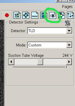
| Contrast and brightness of the active detector. | |
| Status of SEM and FIB column, their respective currents.??? | |
| Symbol for vacuum status in the three main parts, the FIB column tilted to the left, the up-right SEM column, and the main chamber below. Green means vacuum OK. The lock symbol ???????? |
Here are the parameters for the FIB column indicated by the
"ions"-symbol, .
| Select buttons for parameter sets below |
|
| Pump or Vent for loading/unloading samples | |
|
Wake Up starts both SEM column and FIB column,
Sleep shuts them both off.
Please use Sleep when you have finished using the ion-source. It prolongs the lifetime. | |
|
Status for the FIB column, the source is not started,
indicated by the grey bar. Starting will take a couple of minutes,
heating the gallium.
The High Voltage is not on, indicated by the Beam On button is not active and the red indicator light. | |
| Lens Alignment and Source Tilt are not applicable to the FIB column. | |
| Adjust magnification. Couple Magnifications means that the magnification is kept the same when switching between SEM imaging and ion beam imaging. Any graphic drawn in the ion beam quadrant will change size when the magnification is changed in the SEM quadrant (and vice versa). | |
| Stigmation adjustment. Beam Shift is for adjusting image position without moving the stage, important when milling and imaging. | |
| Rotation of image by changing the direction of scanning. | |
| Contrast and brightness of the active detector. | |
| Status of SEM and FIB column, their respective currents.??? | |
| Symbol for vacuum status in the three main parts, the FIB column tilted to the left, the up-right SEM column, and the main chamber below. Green means vacuum OK. The lock symbol ???????? |
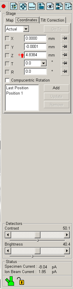
The "Naviagtion"-button is now active.
The stage can be moved interactively in several ways:
| Select buttons for parameter sets below |
|
|
Here the coordinates for the stage can be set and the stage
moved.
There is a red arrow beside the Z-coord., indicating that the Z-position is not yet locked to the working distance. This means that the software does not know how high the sample is, and there is a risk of crashing the sample into the SEM-column. To lock Z to WD, focus on the sample at the current Z, then click the "lock Z to WD"-button. Compucentric rotation means that rotation is made so that center of rotation is in the center of the scanned image. Specific stage positions can be stored in a position list with the Add-button. The stage can always be stopped by pressing 'Esc" on keyboard. | |
How to adjust eucentric positionEucentric position means that when tilting the stage, the same area of the sample is imaged. This is necessary when milling and imaging the milled area.Please note that right mouse-button pressed and moving mouse controls the focus. Also of course the focus-knob on the panel.
| |
| Contrast and brightness of the active detector. | |
| Status of SEM and FIB column, their respective currents.??? | |
| Symbol for vacuum status in the three main parts, the FIB column tilted to the left, the up-right SEM column, and the main chamber below. Green means vacuum OK. The lock symbol ???????? |
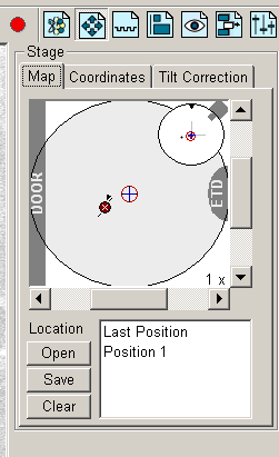
The Map-tab is now displayed.
| Select buttons for parameter sets below |
|
|
Coordinates for the stage can be set in a graphic way.
The big circle is the stub circumference, the smaller circle in the upper right corner shows the tilt of the stage. Positions can be defined and stored in lists, saved to and opened from files. |
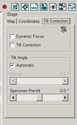
The Tilt Correction-tab is now displayed.
| Select buttons for parameter sets below |
|
|
Dynamic Focus means that when the SEM is scanning across
the tilted sample, the WD (focus) is continuously
varied while the scan is moving from
upper part of image to lower part of image. In this way optimum focus
is maintained over the whole image area, despite the upper areas being
farther away from the column and the lower area being closer to the
column. The image is sharp in all areas.
Tilt Correction means that the SEM image is "streched" in vertical direction, thus showing "correct" geometry as though the image was scanned while being perpendicular to the SEM column.
Tilt Angle on Automatic means that the tilt angle is taken from the
value set in the T-field in the Coordinates tab. Otherwise
it can be set arbitrarily with the value-bar below.
|
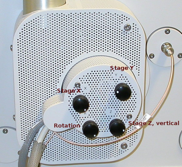
Center of the door to main chamber, where
the
motors and
control knobs are for the sample stage.
| Select buttons for parameter sets below |
| |
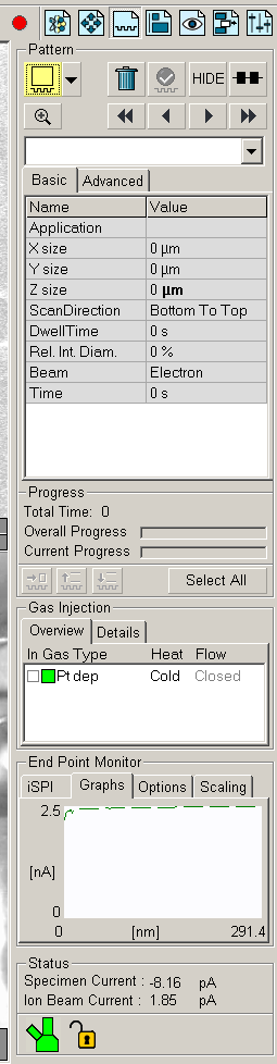
Patterns can be deleted, hidden and patterning can be made in serial or parallell. | ||
| Two Progress bars, one for each single pattern, and one for the total progress of all patterns. | ||
|
Gas Injection, to activate click on Cold, in about XX minutes
the platinum source is hot and emits gas.
To insert nozzle, click in the In-checkbox. The nozzle is adjusted to a position 125 µm from the sample surface if sample is in Eucentric position! Otherwise the nozzle might crash into the sample!!! | ||
| End Point Monitor | ||
| Status of SEM and FIB column. | ||
| Symbol for vacuum status in the three main parts, the FIB column tilted to the left, the up-right SEM column, and the main chamber below. Green means vacuum OK. |
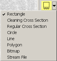
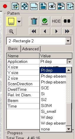
The Pattern-tab with selector for different patterning methods
| Select buttons for parameter sets below |
|
|
After a pattern has been defined, it can be selected and various parameters
for it can be set.
Here the method for patterning is chosen, Pt dep is platinum
deposition, Si would be good for milling a silicon surface.
Please note that the Pt-source should be active at least one hour for stabilizing, before depositioning. |