|
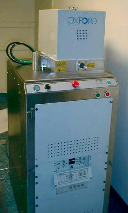
Here is the system seen from the front. Going from top to bottom there are:
- The ICP unit, Inductive Coupled Plasma. The ions are accelerated
not only by the E-field but also by a magnetic coil.
- The chamber with viewing port (small round window).
- Front panel with chamber lift control buttons. The two outermost
blue buttons have to be pressed simultaneously to lift/lower the chamber.
The up/down direction of the chamber is selected with the black knob
to the left. At the center is
the emergency shutdown switch.
- System power on/off buttons.
- Perforated frontpanel for RIE RF auto match unit. This matches the
radio frequency power input to the plasma for as little loss (reflection)
as possible.
- Control panel for RIE and ICP RF auto match units. The auto match unit
for the ICP is located in the housing at the top of the system.
- Control panel for Turbo pump (partly hidden by folded down protective cover
for auto match unit control).
- Front panel for RF generators (at lower edge of image).
Note!
Here two power switches have been added, one for each RF generator. This
is because the generators are quite noisy, and cannot be on continously.
The switches should be turned on just before an acutal etch, and switched
off when the etching is over.
|