- Mount a sample onto the sample holder.
- Mount an appropriate probe into the standard probe holder (see Prepare and Load the Probe Holder for details).
- Click the Select Experiment icon to open the Select Experiment window.
PeakForce KPFM (PeakForce Frequency Modulated-Kelvin Probe Force Microscopy) is a combination of Peak Force Tapping Mode and frequency modulated KPFM (FM-KPFM) mode.
PeakForce KPFM measures surface potential or work function using a Lift Mode Surface Potential Imaging (AM-KPFM) variation of the FM-KPFM Imaging mode while simultaneously providing correlated nanomechanical property information using the Bruker's proprietary Peak Force Tapping Mode.
PeakForce KPFM leverages the advantages of PeakForce Tapping:
Because of PeakForce's direct force control, softer probes may be used in this mode, thereby increasing sensitivity.
Bruker recommends PFQNE-AL probes for PF FM-KPFM measurements.
Prepare the sample as described in Electrical Sample Preparation.
|
|
|
|
|
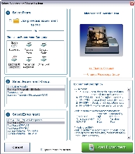
(Hover over the image to view larger)
Figure 1: The PeakForce KPFM Select Experiment window
|
|
|
|
|
|
|
|
|

Figure 2: Align the laser on the cantilever and place the crosshair there.
|

Figure 3: The HSDC window, indicating that a cantilever tune operation is underway.
|
|
|
|
|
|
NOTE: The stored data is unaffected by the Potential Offset. I.e. offline measurements do not see this input.
|
A sample result showing the surface potentials (work functions) of three different materials is shown in Figure 4.
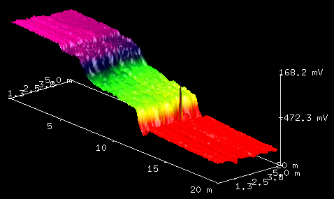
Figure 4: PeakForce KPFM scan of a Au-Si-Al (left to right) sample.
Automatic frequency selection is the default for PeakForce KPFM imaging. You may wish, however, to manually select an operating frequency. To do this:
|
|
|
|
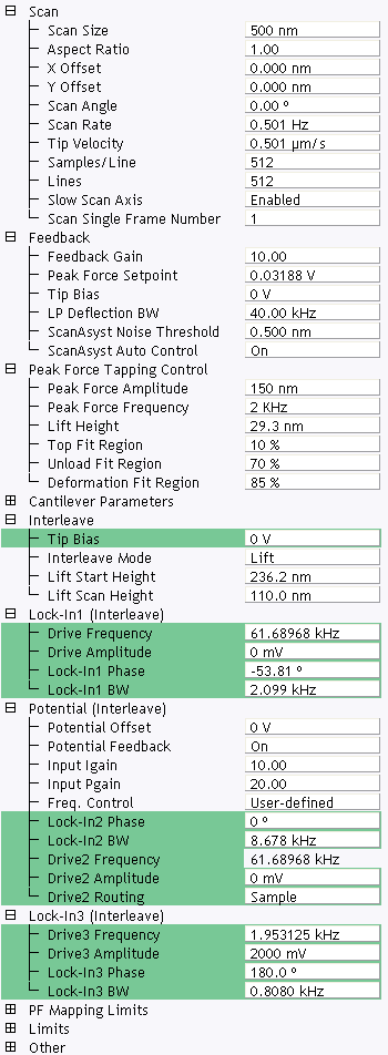
Figure 5: Selecting User-defined Frequency Control
You can manually select the operating frequency of the LiftMode. For details, refer to Advanced PeakForce KPFM-AM Operation.
You may wish to manually adjust the parameters shown in Table 1.
| Parameter | Description |
|---|---|
| Lock-In1 BW | Needs to be smaller than twice the Drive 3 Frequency which is fm in Figure 8 of FM-KPFM Imaging. This lets the Lock-In respond to f0 while filtering f0 ± fm. If the Lock-In BW is too low, the tracking ability will be reduced. Automatic Freq. Control is thus easier to use than User-defined Freq. Control. |
| Lock-In2 BW | Needs to be larger than four times the Drive 3 Frequency which is fm in Figure 8 of FM-KPFM Imaging. This is used to include the first and second harmonics, f0 ± 2fm. Extra bandwidth of Lock-In2 does not degrade image quality as Lock-In3 follows. |
| Lock-In3 BW | Lock-In3, cascaded with Lock-In2, is used for the surface potential feedback. |
| Drive3 Amplitude | Higher Drive3 Amplitudes will result in higher signal-to-noise ratios. |
Table 1: Adjustable FM-KPFM parameters
| www.bruker.com | Bruker Corporation |
| www.brukerafmprobes.com | 112 Robin Hill Rd. |
| nanoscaleworld.bruker-axs.com/nanoscaleworld/ | Santa Barbara, CA 93117 |
| Customer Support: (800) 873-9750 | |
| Copyright 2010, 2011. All Rights Reserved. |