The Indent setpoint parameter serves as a multiplier to the Amplitude setpoint and affects the point at which the indentation or force plot is triggered. It is in effect only for nanoindentation and is disabled at all other times.
Nanoindentation uses the TappingMode function to find the surface when executing an indentation. Before penetrating the surface, the cantilever is oscillated using the and previously set in the Scan view. Then, the tip is moved toward the sample, until the amplitude of oscillation of the cantilever has been reduced to a predetermined amount. This predetermined amount is specified by the Amplitude setpoint, also previously set in the Scan view, and by the Indent setpoint, and is equal to the Indent setpoint times the Amplitude setpoint.
For example, if the Amplitude setpoint is set to 200 mV and the Indent setpoint is set to 0.9, then the predetermined amount would be 180 mV (90% of the Amplitude setpoint). The Z position at which the amplitude is reduced to this predetermined amount is the surface contact point. Finally, with the oscillation off, the tip is forced into the sample until the cantilever deflection, measured relative to the deflection at the surface contact point, is equal to the Trigger threshold (Figure 2).
The Indent setpoint is useful in cases where the free-air (pre-contact) part of the deflection curve is not flat. If this is the case, the maximum deflection and force during indenting will vary depending on where the indentation was triggered. The Indent setpoint allows the user to move the surface contact point closer to the point where cantilever deflection begins (see Figure 2). A typical range for Indent setpoint is 0.5–1.0; a good default value to use is 0.9.
During the tip’s descent to the surface, the graph will reveal the surface contact point as a vertical yellow line near the ramped (sloped) portion of the plot (see below).
Changes to the Indent setpoint will cause shifts in the surface contact point on the force plot: increasing the Indent setpoint will shift the surface contact point rightward on the plot; decreasing the Indent setpoint will shift the surface contact point leftward (Figure 2). Generally an Indent setpoint of 0.9 is recommended.
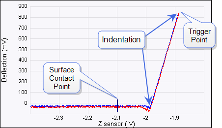
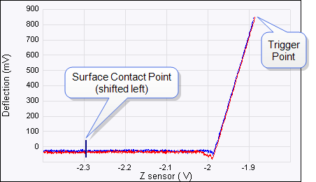
Figure 2: Changes in Indent Setpoint will shift the surface contact point left or right
 Trig[ger] Threshold
