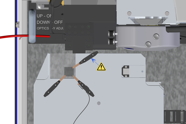
Figure 1: Sample clamp arrangement
![]()
Figure 2: Sample clamp with two spacer magnets installed below.
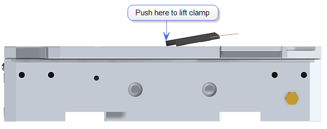
Figure 3: Push down at the rear of the clamp to release it.
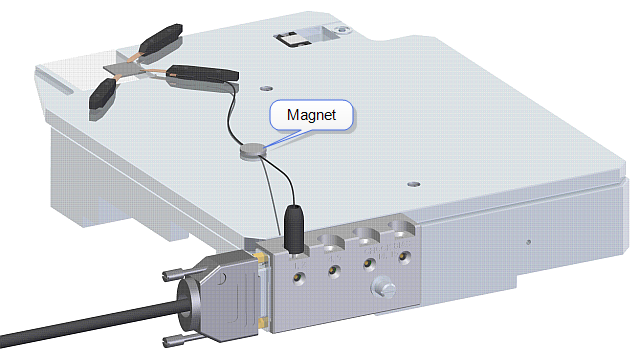
Figure 4: Hold the cable to the chuck with a 1/2" magnet
The maximum Y axis travel is 30 mm, shown in Figure 5.
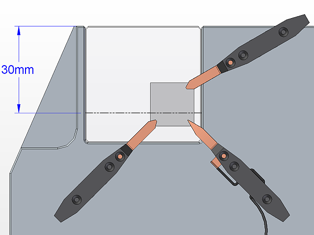
Figure 5: Maximum Y axis travel
Bruker suggests that you constrain the clamps so that they intrude no more than 2 mm on each side of the sample. See Figure 6. Placing the clamps further inboard of the sample edges will reduce the available travel.
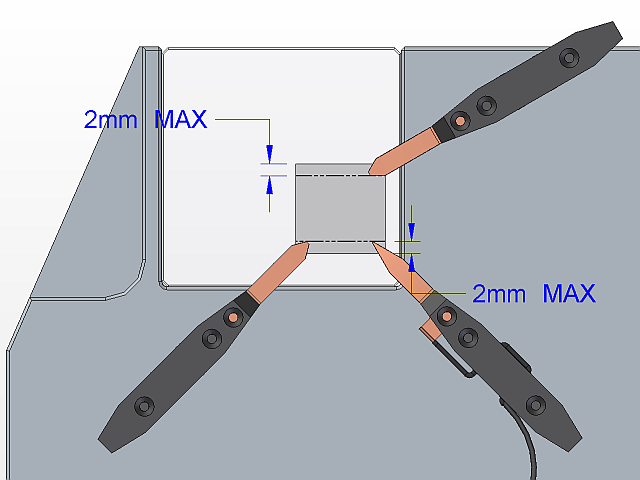
Figure 6: Suggested clamp constraints
The area that is unavailable after placing the clamps 2 mm inboard is 4.25 mm in the Y axis and is illustrated in Figure 7.
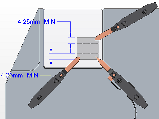
Figure 7: Unavailable area with clamp locations as described in Figure 6.
|
The focus can be adjusted from approximately the top of the chuck surface to about 3 mm above it.
|
|
|
|
|
|
|
|
|
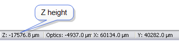
Figure 8: Z height display in the NanoScope status bar
|
|
NOTE: The camera image may differ depending on the sample opacity.
|
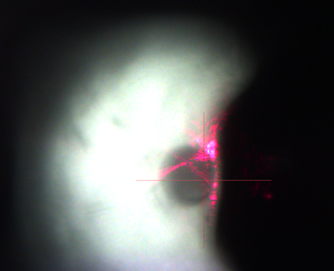
Figure 9: Optical fiber visible at low illumination
|
|
|
Because of the limited spot size (200 μm diameter), the light spot must be centered in the scan range especially for experiments using large sample scan sizes.
The light spot position must be readjusted after a probe change.

Figure 10: The Backside Illumination Optics Assembly stages Clockwise rotation of the Z translation knob moves the Z stage down while counterclockwise rotation moves it up.
If you see a large X-Y movement while adjusting Z, check both the vacuum holding the Backside Illumination Optics Assembly to the granite base (by pulling on the handles) and the vacuum holding the X-Y stage (by pulling on the Y translate screw).
| www.bruker.com | Bruker Corporation |
| www.brukerafmprobes.com | 112 Robin Hill Rd. |
| nanoscaleworld.bruker-axs.com/nanoscaleworld/ | Santa Barbara, CA 93117 |
| Customer Support: (800) 873-9750 | |
| Copyright 2010, 2011. All Rights Reserved. |