There are two methods of obtaining calibrated, quantitative results from PeakForce QNM. The first method (the relative method) avoids accumulated errors that can cause errors in modulus measurements, but has the downside in that it requires a reference sample that can be measured by the same probe as the unknown sample.The second method (the absolute method) does not require a reference sample, but requires accurate measurement of the tip end radius (typically by scanning an artifact sample like TipCheck) and spring constant (typically with thermal tune for soft cantilevers). Both methods require measurement of the deflection sensitivity on a hard sample.
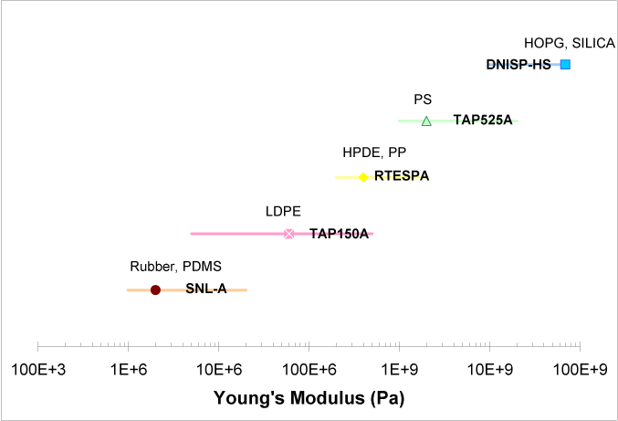
For both methods, it is important to choose a probe that can cause enough deformation in the sample and still retain high force sensitivity. Figure 1 shows the recommended probes and the modulus range over which they work best.
Figure 1: Modulus ranges covered by various probes. The modulus of the reference sample for each range is indicated as well.
| Symbol | Chemical Name |
|---|---|
| PDMS | Polydimethylsiloxane |
| LPDE | Low-density polyethylene |
| HPDE | High-density polyethylene |
| PP | Polypropylene |
| PS | Polystyrene |
| HOPG | Highly Oriented Pyrolytic Graphite |
Table 1: Legend
The relative method of calibration uses a sample of known modulus to obtain the ratio of spring constant to the square root of tip end radius. It is still important to accurately calibrate the deflection sensitivity in order to obtain modulus results. An outline of the procedure follows:
The absolute procedure is very similar to the relative procedure except for two important differences:
| www.bruker.com | Bruker Corporation |
| www.brukerafmprobes.com | 112 Robin Hill Rd. |
| nanoscaleworld.bruker-axs.com/nanoscaleworld/ | Santa Barbara, CA 93117 |
| Customer Support: (800) 873-9750 | |
| Copyright 2010, 2011. All Rights Reserved. |