Nikon Microscope ME600 with DIC
(Differential Interference Contrast)
The microscope is primarily intended for inspection of wafers or chips after
development and/or evaporation. It is equipped with an incident (epi)
illuminating
unit (light is coming from above the specimen) with a
Differential Interference Contrast option.
It is also equipped with
Dark Field
option.
Beam-path for Bright-Field illumination in epi mode
Caution! Careful handling of the stage
Framegrab- and measurement
software, short instructions
There are five objectives from the Nikon CF Plan BD DIC series with data
as follows:
|
Magnification
| Numerical Aperture
| Working Distance [mm]
| Magnification at full screen
|
|---|
| 5 ×
| 0.13
| 10.0
| 260 ×
|
| 10 ×
| 0.3
| 6.5
|
| 20 ×
| 0.46
| 3.1
| 1000 ×
|
| 50 ×
| 0.8
| 0.54
|
| 100 ×
| 0.9
| 0.39
|
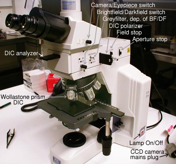
Here is the microscope with most of its knobs and switches labeled.
If we start at the lower right corner there are:
- Lamp On/Off switch. It is of course important to switch the lamp of
after use to prolong its lifetime. This is NOT a mercury lamp,
so it can be switched on and off with no special consideration for warm-up
time etc.
If we then go from left to right in the image we have:
- DIC analyzer. It is a polarizer, here shown in its out-position,
meaning that it is not active.
- Wollastone prism. A bi-refringent prism dividing the polarized light
into two partial beams. See separate
description of DIC.
The outer knob is for adjustment of the optimum coloring of the sample.
Very briefly: when studying reflecting samples with
areas etched to different depths,
DIC-imaging transform the varying depths to a different colors.
- Camera switch. Switches the light-path between eye-pieces and CCD-camera.
Here shown in the eye-piece position.
- Bright-field/Darkfield (BF/DF) switch, see separate
description of darkfield illumination.
Note the coupling to the grey-filter.
Here shown in the BF position.
- Grey-filter, ND (neutral density). Coupled to the BF/DF switch.
This filter reduces the
brightness when looking in BF and is removed when switching to DF. This is
so because usually more light is required when using DF. The grey-filter can be
separately removed by pulling the lever outwards.
Here shown in the inserted (reducing) position.
- DIC polarizer. First polarizer in the light-path. Polarizes the illuminating
light so the Wollastone-prism can separate it into two parts.
It has a wheel at the edge making it possible to adjust the direction
of polarization for optimum color saturation.
Here shown in its out-position, i.e. not active.
- Field stop, limits the size of the illuminated field on the sample,
should be matched to the viewing field for best contrast.
- Aperture stop, sets the amount of light reaching the sample,
sets the top angle of the cone of illuminating light that reaches the
sample. Can be used to match that angle with the top angle for the cone
of light collected by the objective. This gives a slight increase in
resolution and contrast.
See also
Beam-path of Bright-field illumination
In summary; the above image shows the microscope set up for bright-field (BF)
imaging, the DIC and DF options are disabled. The important settings are:
- DIC analyzer out
- Wollastone prism out
- DIC polarizer out
- BF/DF switch in BF position
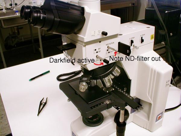 Here the microscope is set up for Dark-Field imaging.
Note the BF/DF switch out, in DF position. The ND-filter is following the
BF/DF switch out. Everything else as in the previous picture.
Here the microscope is set up for Dark-Field imaging.
Note the BF/DF switch out, in DF position. The ND-filter is following the
BF/DF switch out. Everything else as in the previous picture.
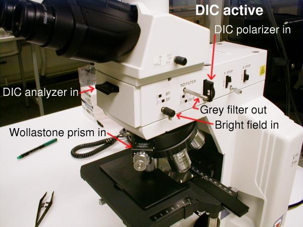 DIC imaging setup
- DIC analyzer in
- Wollastone prism in
- DIC polarizer in
- BF/DF switch in (BF)
- ND-filter pulled out for more brightness (optional)
Adjust for optimal coloring with knob on Wollastone prism and edge-wheel
on DIC polarizer.
The height variations on the sample surface is coded
as varying color in the image.
Very roughly described: the DIC polarizer is rotated for the amount
of color in the image. Usually the maximum color is
when setting the wheel at the dot marker.
The knob for the Wollastone prism is rotated to select what color
scale is useful. It ranges from dark bluish to deep reds.
Please note that color disappears at the extreme end positions of the knob.
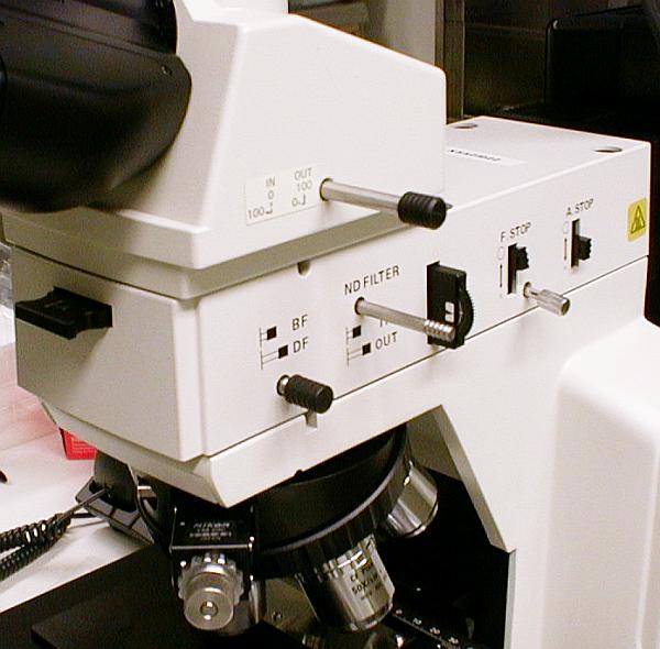
A closer view of settings in DIC mode, all labels on microscope
are readable
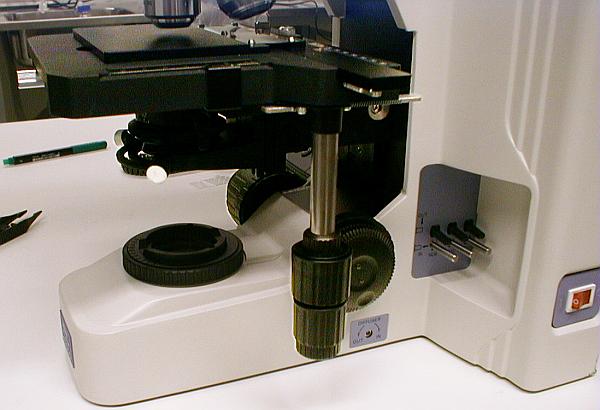
The controls for the stage, two ganged knobs for left/right and
up/down movement of the stage are visible in the center.
Behind them are the focusing controls.
Caution! Please be careful when you
move the stage to its outer limits. Do not force it against
its end-limits. This can cause deformation of the mechanical coupling
resulting in play in the stage.
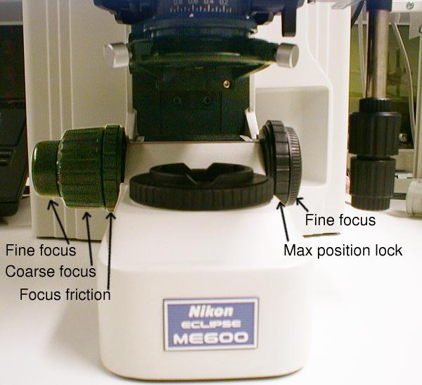
Here are all the focusing controls shown and labeled.
From left to right:
- Fine focus knob, the scale is in microns
- Coarse focus wheel for long vertical movements of the stage.
Note! Care should be taken not to press the sample
into the objective. This might destroy both sample and objective.
See below "Max position lock".
- Focus friction. Adjust how hard it is to move the stage with the coarse
focus wheel.
- Maximum upper position lock. Useful to avoid to run the sample into
the objective. Release the lock and raise the stage as far
as you think is safe with the coarse focus wheel. Then set the lock.
Now it is impossible to raise the stage above this level, and the sample
will never touch the objective.
- Fine focus wheel. For right-hand use.
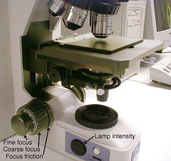 The focusing controls from another angle.
Also the lamp intensity control is shown. The white button next to it
is the "Photo"-switch, it bypasses the intensity control and
sets such an intensity that
the color balance of the halogen lamp is suitable for true-color photography.
This is not very important for DIC-imaging.
The focusing controls from another angle.
Also the lamp intensity control is shown. The white button next to it
is the "Photo"-switch, it bypasses the intensity control and
sets such an intensity that
the color balance of the halogen lamp is suitable for true-color photography.
This is not very important for DIC-imaging.
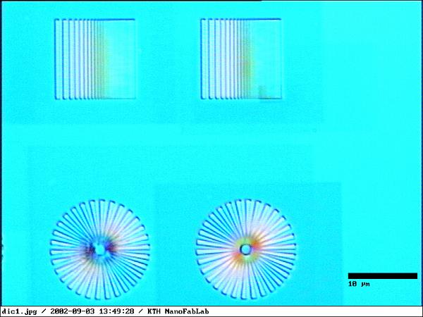 A DIC image of some patterns made with e-beam lithography.
Imaged with 100X/0.9 objective.
Pattern is made on a SiN membrane, 100 nm thick. E-beam resist is ZEP, 120
nm thick, pattern was exposed and developed. The pattern was then filled
with 110 nm of Ni by electro-deposition.
A DIC image of some patterns made with e-beam lithography.
Imaged with 100X/0.9 objective.
Pattern is made on a SiN membrane, 100 nm thick. E-beam resist is ZEP, 120
nm thick, pattern was exposed and developed. The pattern was then filled
with 110 nm of Ni by electro-deposition.
Sample courtesy of Anders Holmberg, Biomedical &
X-ray Physics, KTH
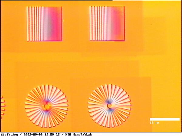 Same sample with different settings of Wollastone prism and
DIC polarizer.
Same sample with different settings of Wollastone prism and
DIC polarizer.
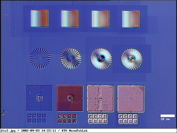 Same sample imaged with the 50x/0.8 objective.
Also new settings
for the Wollastone prism and the DIC polarizer.
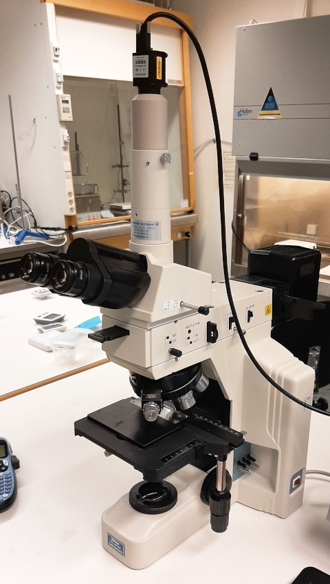
The whole microscope with CCD-camera
Anders Liljeborg
Albanova Nanolab, KTH, SU.