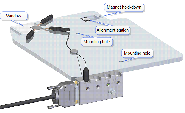
The Transparent Bed Chuck Assembly, shown in Figure 1, extends over the rear of the Dimension Icon's chuck base to allow light from the Backside Illumination Optics Assembly to pass through the window in the chuck to the bottom of the sample.
Figure 1: The Transparent Bed Chuck Assembly
A replacement alignment station, shown in Figure 1, is provided because the transparent bed chuck interferes with the standard alignment station.
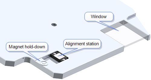
A magnet hold-down, shown in Figure 2, is provided to hold small sample pucks.
Three low profile clamps, shown in Figure 3, are provided to hold the sample to the chuck. Two of these clamps are electrically isolated while a third also provides electrical contact to the sample. These clamps are optimized for samples that are 1 mm thick. A second clamp/probe is supplied for experiments requiring two contacts to the sample.
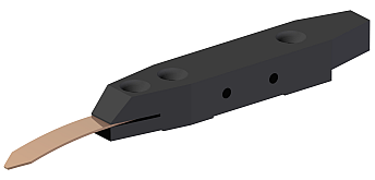
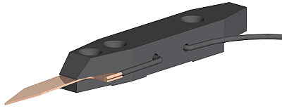
Figure 3: Low profile sample clamp (top) and clamp/probe (bottom)
A terminal block, shown in Figure 4, is provided to electrically connect your sample to either chuck bias or an external circuit. Two jack points are available for each position on the terminal block: a connection on the top and a connection at the front. The left jack pair is connected to pins 1 and 2 of the DB-15 connector at the left of the terminal block while the jack pair to the right of that is connected to pins 4 and 5. The two jack pairs at the right are connected to the chuck and pins 14 and 15.
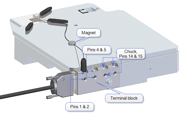
A disk magnet, shown in Figure 4, is provided to hold the wire lead from the probe onto the chuck.
| www.bruker.com | Bruker Corporation |
| www.brukerafmprobes.com | 112 Robin Hill Rd. |
| nanoscaleworld.bruker-axs.com/nanoscaleworld/ | Santa Barbara, CA 93117 |
| Customer Support: (800) 873-9750 | |
| Copyright 2010, 2011. All Rights Reserved. |