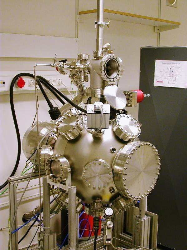
Rod-feed E-gun deposition system "Sputnik"
Responsible:
Taras
Golod,
Anders
Liljeborg
The second deposition system in the Albanova Nano-Fab-Lab is a rod-feed
e-gun system with only aluminum as deposition material. It has been
named "Sputnik" after the shape of the main vacuum chamber.
It has a large turbo pump (2000 l/min) and can deposit material at
vacuum of 10-7 mBar. Normal idle vacuum is 5 × 10⁻⁹
mBar.
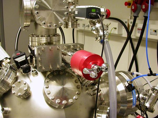
It has options of cleaning sample prior to deposition with an ion-argon gun,
and oxidation can be made via an oxygen-line attached to the load-lock
part.
Venting is made of both load-lock and main chamber with Albanova central
nitrogen supply.
Loading is done at the top load-lock and sample is lowered into center of
main chamber with the vertical transfer rod at the top.
Deposition is made with the gate valve between load-lock and main chamber
open, i.e. there is no actual transfer of samples as in the first
deposition system.
Load / unload procedure
Important to rotate transfer rod before lifting,
description.
Rod feed E-gun system, deposition procedure
Rod feed E-gun,
manufacturers manual
Rod feed E-gun,
schematic 1
schematic 2
schematic 3
3 cm Argon-ion-gun
Oerlikon Leybold T1600 turbo manual, replacing noisy
Varian 2000 l/s turbo.
Venting and pump down of main chamber
(Argon-ion-gun, parameter settings removed
from system)

Overview of deposition system
Load-lock door open

Liquid nitrogen used in the cryo-shroud surrounding
the e-gun.

At the top: vent valve for load-lock
Middle: vacuum gauge for load-lock
Right: Valve for load-lock pump
Gate valve at the center, valve between load-lock and main chamber
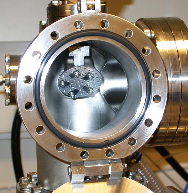
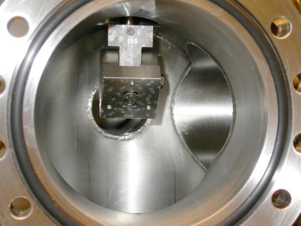
Load-lock door open, sample holder can be seen inside load-lock.
Sample holder is easily removed, it is a snap-in fitting with
magnetic fastening.
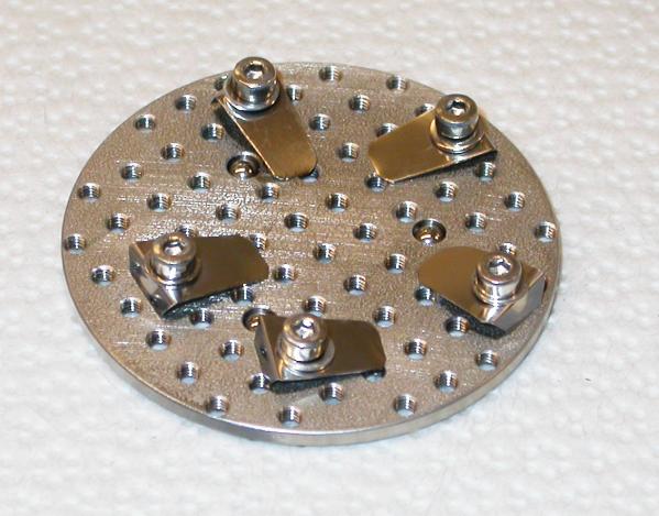
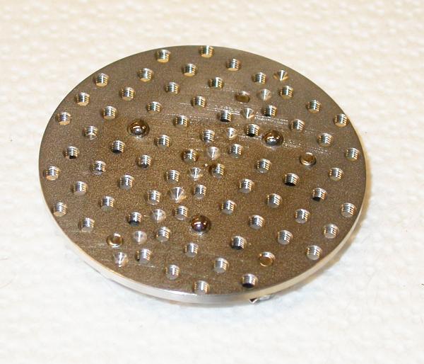
Sample holder, similar clamps for sample as in Eurovac deposition system
Back-side of sample holder, note the three small balls that fit
into corresponding depressions in the base
Base of sample holder at end of transfer rod (in upper position).
Note the three depressions, it is
very important
that the holder is
securely fitted into these.
The holding magnet can be seen at the center of the base.
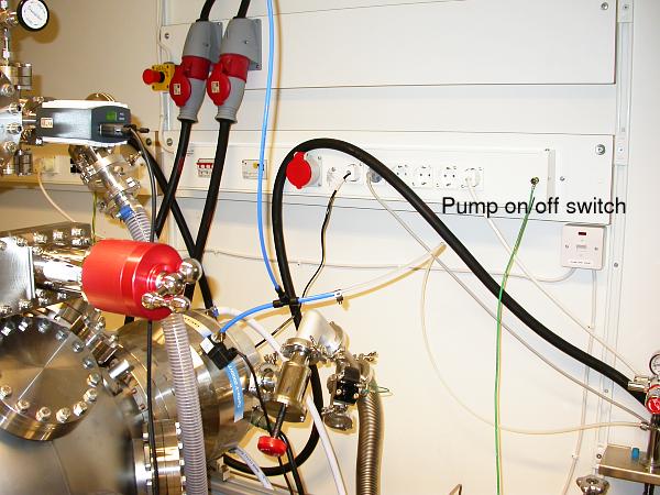
On/off switch for load-lock pump mounted on wall
Load / unload procedure
Normally the system should be left with the gate valve open, so both
load-lock and main chamber are pumped continuously.
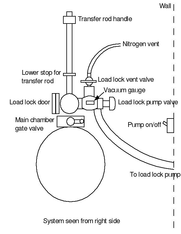
Schematic overview, used for load/unload procedure
Load procedure
- Close main chamber gate valve.
- Check that load-lock pump valve is closed.
- Loosen the locking screw of the load-lock door,
this is to avoid
overpressure at the end of venting the load-lock.
- Slowly open load-lock vent valve.
- Check the vacuum gauge, when it reaches E-2 mBar you
can open the vent valve a bit more to quicken the venting.
- When the load-lock door gets loose due to atmospheric pressure
in load-lock, close the vent valve.
- Open load-lock door and take out the sample holder. It is held
in position by a magnet and three small balls fitting into corresponding
depressions.
- Mount your sample on the holder using clamps and screws.
- Insert the sample holder on the transfer rod. Make sure the position
is correct, i.e. the balls must fit into the depressions.
- Close load-lock door and press it tight with the locking screw, so that
the O-ring is touching the door everywhere. Do not over-tighten.
- Open load-lock pump valve fully.
-
Start load-lock pump with power switch mounted on the wall.
-
Wait until vacuum gauge shows about 5E-3 mBar.
-
Close load-lock vent valve.
-
Open main chamber gate valve.
-
Shut off load-lock pump with switch mounted on wall.
-
Loosen the locking ring immediately under the ring of the transfer rod.
-
Slowly let the transfer rod sink down into the main chamber.
-
Let transfer rod ring rest on the lower stop ring.
Warning: never loosen the lower stop ring!
It is adjusted so that the sample holder is positioned at center
of deposition beam.
-
Start depositing.
Rotate transfer rod so pointer stick is directed towards back wall
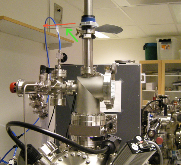
Always aim the pointer stick (green arrow) towards the back wall
(direction of red arrow) before starting to lift the transfer rod.
Unload procedure
-
Shut off E-gun system.
-
Rotate the transfer-rod so sample holder is facing away from E-gun,
angle indicator at 180 deg. The pointer stick should be aimed at the
back wall, see picture above.
-
Lift up transfer-rod to its top-most position and lock it there by
tightening the lock-ring.
-
Close main chamber gate valve.
-
Check that load-lock pump valve is closed.
-
Loosen the locking screw of the load-lock door,
this is to avoid
overpressure at the end of venting the load-lock.
- Slowly open load-lock vent valve.
- Check the vacuum gauge, when it reaches E-2 mBar you
can open the vent valve a bit more to quicken the venting.
- When the load-lock door gets loose due to atmospheric pressure
in load-lock, close the vent valve.
-
Open load-lock door and take out your sample on the sample holder.
-
Remove your sample from the sample holder.
-
Insert the sample holder on the transfer rod. Make sure the position
is correct, i.e. the balls must fit into the depressions.
- Close load-lock door and press it tight with the locking screw, so that
the O-ring is touching the door everywhere. Do not over-tighten.
- Open load-lock pump valve fully.
-
Start load-lock pump with power switch mounted on the wall.
-
Wait until vacuum gauge shows about 5E-3 mBar.
-
Close load-lock vent valve.
-
Open main chamber gate valve.
-
Shut off load-lock pump with switch mounted on wall.
In this way you leave the complete system (including load-lock)
being pumped continuously for best vacuum.
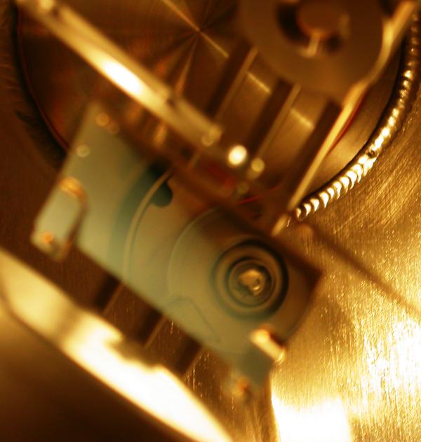
View through view-port, 45-deg. mirror on top of cryo-shroud
showing top of aluminum rod in e-gun.
At lower left is top of cryo-shroud (out-of-focus).
In approximate center is mirror (out-of-focus) showing top of
e-gun with alu-rod.
Above and to right is the shutter seen edge-on (out-of-focus).
At the top is the sensor of the thickness monitor (out-of-focus).
Anders Liljeborg
Nanostructure Physics, KTH.