Preparing a Dimension Series AFM for a Realtime Scan
| |
Once you’ve created the workflow and scan parameters, prepare the system to scan. This includes aligning the laser, adjusting the photo detector, locating the cantilever tip with the optical microscope, and focusing the optical microscope on the surface. If you have not yet learned these procedures, refer to your Dimension Microscope Manual and/or SPM Training Notebook.
For details on using the Realtime Scan Views, see Real-time Views.
- Mount the probe into the cantilever holder.
- Mount the cantilever holder onto the end of the scanner head.
|

|
Click the Setup icon in the Workflow Toolbar.
|
| |
- This opens the Setup window, shown in Figure 1. The Setup view divides probe setup into several steps.
|
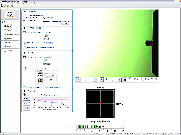
Figure 1: The Setup Window
| |
- The first step is Load Probe.
- Click the Change Probe button.
- The opens the Change Probe window, shown in Figure 2.
|
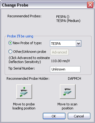
Figure 2: The Change Probe window
| |
- The Change Probe window will recommend a probe type for your imaging mode
- Click a radio button to select your probe. You have two choices:
- Click New Probe of type and select a probe from the drop-down list.
- If the probe that you are using is not listed, click Other/Unknown Probe, then click the Advanced button.
- Optional: Enter the probe serial number (this is a recommended best practice). The capture directory will save the tip serial number with your data.
Several panels in the Setup window help you through the process:
- The Video panel, shown in Figure 1, displays an image of the area around the cantilever.
- The Meter panel, shown in Figure 3, displays the signals on the quad photo detector and the laser sum signal.
|
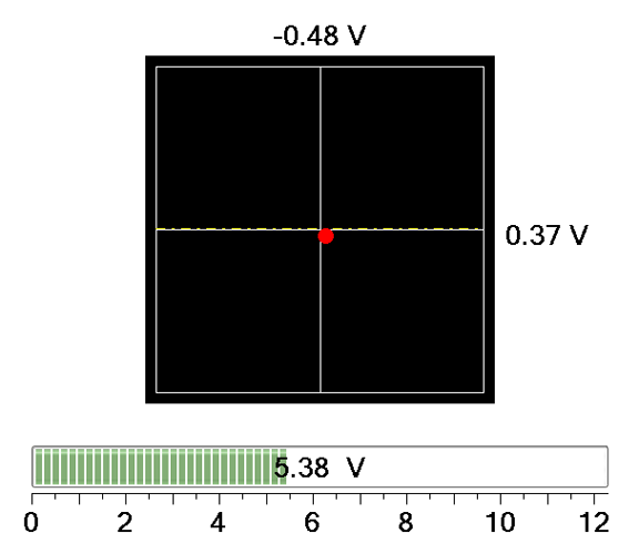
Figure 3: The Meter panel in the Setup window
| |
- The align instruction video, accessible through the Align panel (Figure 4) and shown in Figure 5, plays a short instructional movie showing the effects of moving the laser and photo detector alignment knobs.
|
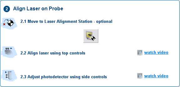
Figure 4: Watch Video Commands in the Align Panel
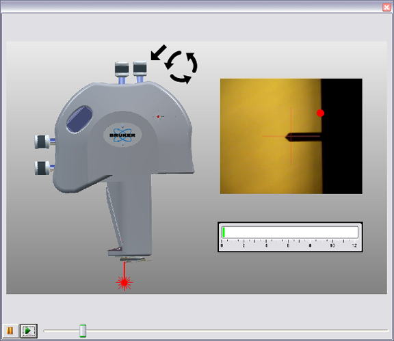
Figure 5: The align instruction movie window
| |
- The optics panel, shown in Figure 6, has buttons to zoom or unzoom the camera and buttons to adjust the sample illumination LED. Zooming out may aid in locating the tip.
|
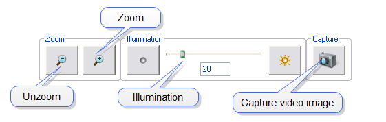
Figure 6: The optics panel
| |
- The video panel, shown in Figure 1, displays an image of the area around the cantilever.
The Focus Controls panel, shown in Figure 7, focuses the optics on the probe tip and thus knows the Z position of the probe tip. This knowledge is needed to successfully engage the probe tip onto your sample.
|
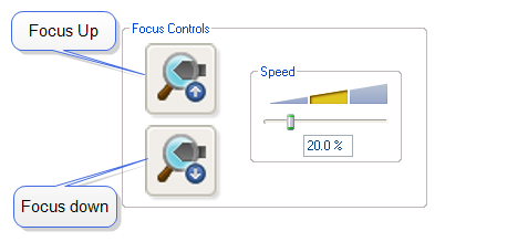
Figure 7: The Focus Controls panel
| |
The Focus Select panel, shown in Figure 8, tells the system if you are focusing on the Tip or the Tip Reflection.
|
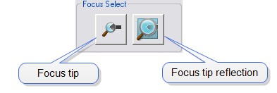
Figure 8: The Focus Select panel in the Setup window
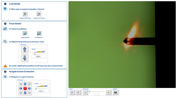
Figure 9: The Navigate Window
| |
- Focus the optics on the sample surface using either the trackball or the Scan Head arrows, shown in Figure 10, in the Navigate View. If you have used the Alignment station, the stage will prompt you before moving back to the sample position.
|
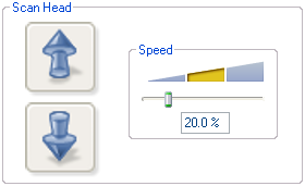
Figure 10: Focus: Z Motor Controls
| |
- To use the track ball, roll the trackball up or down while holding down the bottom-left button. To use the Z Motor arrows, click and hold them down. You can use the speed controls in the Z Motor area to adjust the speed. This adjustment raises or lowers the Z stage on which the SPM and optics are mounted.
- To focus on the sample Surface (normal operation) or the Tip Reflection (for extremely clean samples), change the Focus Select parameter accordingly.
|

Figure 11: The Navigate Focus Select Panel
| |
NOTE: For reflective or semi-reflective samples, the tip reflection is easier to bring into focus than the surface, especially if the sample is very flat or clean.
CAUTION: When moving the SPM stage up and down, it is possible to crash the tip into the surface. To prevent a crash while focusing on the surface, watch the optical image and tip-to-sample proximity. The sample should be in focus when the tip is 1mm (1000 µm) above the surface.
- For samples which are difficult to bring into focus, move to an edge of the sample, which is easy to find in the optical image, and bring the top of the edge into focus.
- Move the X-Y stage to align the desired location on the sample under the crosshairs either by using the trackball without holding down any buttons or by using the XY Stage Control arrows, shown in Figure 12, in the Navigate View.
|
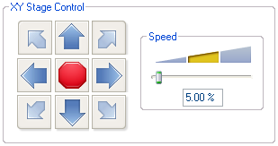
Figure 12: XY Stage Controls

|
- If you are using TappingMode, click the Tune icon. Check your parameters in the Auto Tune list.
|
| |
- Click the Auto Tune button. Notice that the status bar at the bottom of the NanoScope software window says “Cantilever Tuning” during automatic tuning. When tuning is complete, click Exit in the Cantilever Tune dialog box.
|
Previous Step:
Starting NanoScope Software
Next Steps:
Scanning and Scan Parameters
Capturing An Image
Analyzing an Image With Section Analysis
ASCII Export
High Resolution Imaging
| www.bruker.com
|
Bruker Corporation |
| www.brukerafmprobes.com
|
112 Robin Hill Rd. |
| nanoscaleworld.bruker-axs.com/nanoscaleworld/
|
Santa Barbara, CA 93117 |
| |
|
| |
Customer Support: (800) 873-9750 |
| |
Copyright 2010, 2011. All Rights Reserved. |
Open topic with navigation