Force Curve Procedure
Ramp Settings
| |
To obtain force curves, it is necessary to first engage in Scan Mode using one of the Scan Views (see Preparing a Dimension Series AFM for a Realtime Scan), then switch to Ramp mode. If you want to calibrate deflection sensitivity, use a hard sample in the following procedure.
|

|
- Activate Ramp, mode by clicking the Ramp icon in The Workflow Toolbar. This causes the system to stop scanning, and the probe to position above the center of the previous image.
|
| |
See Ramp Parameter List for a discussion of the Ramp Parameter List parameters. When in Ramp mode, a ramp- specific menu also displays, the Ramp menu. See Ramp Menu for more information.
- Enter the following parameter settings in the designated panels of the Ramp Parameter List:
- In the Ramp panel select:
|
| Parameter |
Setting |
|
Ramp Output
|
Z |
|
Ramp size
|
1.00µm |
|
Z scan start
|
0nm |
|
Ramp Rate
|
1.00Hz |
|
Number of samples
|
512 |
| |
- In the Channel 1 panel select:
|
| Parameter |
Setting |
|
Data Type
|
Deflection Error |
|
X Data Type
|
Z |
|
Display Mode
|
Deflection Error vs. Z |
Gather Force Curves

|
- Click the Ramp Continuous icon on The NanoScope Toolbar or select Ramp > Ramp Continuous, from The Menu Bar.
|
| |
- While watching the Ramp Plot and the Real Time Status bar graph (see Figure 1), increase the Z scan start parameter to move the tip closer to the sample.
|
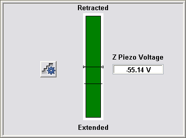
Figure 1: Real time status bar graph
| |
- When the force curve suddenly rises, the tip has reached the surface (see Figure 2).
|

Figure 2: Force Curve

|
- Click the Capture icon to save the force curve. Make note of the file name shown in the status bar (lower right corner of the window).
|
Calibrate Deflection Sensitivity
It is often necessary to calibrate the deflection sensitivity of a force curve. The deflection sensitivity depends upon several factors, such as the position of the laser spot on the cantilever, so it needs to be calibrated each time you change the probe. Use the following procedure to determine the deflection sensitivity:
| |
- Move two cursors onto the Deflection vs. Z plot (see Figure 3).
- Arrange the cursors so that they surround the contact (steepest) portion of the graph (see Figure 3).
|
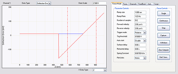
Figure 3: Force Curve Cursors

|
- Click the Update Sensitivity icon in the NanoScope toolbar or select Ramp > Update Sensitivity. The software will automatically calculate the deflection sensitivity and open the Set Realtime Channel Sensitivities window (see Figure 4).
|
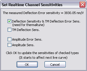
Figure 4: Deflection Sensitivity Dialog Box
| |
- Click OK to accept this deflection sensitivity in the dialogue box that displays, and it will automatically be entered into the Deflection Sensitivity parameter in the Channels panel to the right of the plot (see Figure 3).
- Replace the hard sample with the sample you wish to analyze. The deflection sensitivity will remain applicable as long as the position of the laser spot on the cantilever does not change.
|
Next:
Ramp Parameter List
Ramp Menu
| www.bruker.com
|
Bruker Corporation |
| www.brukerafmprobes.com
|
112 Robin Hill Rd. |
| nanoscaleworld.bruker-axs.com/nanoscaleworld/
|
Santa Barbara, CA 93117 |
| |
|
| |
Customer Support: (800) 873-9750 |
| |
Copyright 2010, 2011. All Rights Reserved. |
Open topic with navigation